|
This circuit is the 12-bit binary counter which used 4040B.
The number of the pulses of the input can be confirmed by seeing it with the eyes by putting the light-emitting diode
to the output of the counter.
It is the function only of it but it is useful.
Because it is the 12 bits, the highest rank counter is divided to 1/4096. Because it is, in the highest rank, the signal
of 4KHz can be seen in the about 500-millisecond blink.
At the input circuit, it is protecting the counter IC from the excessive input voltage with the resistor and the Zener
diode.
| circuit diagram |
|
| Pattern circuit |
|
7-segment displays
A 7 segment display is manufactured encapsulating 7 LEDs inside a single case. Each LED is given a shape and position which
makes it a separate "segment": lighting teo or more segment in different patterns, we can read all digits from 0
to 9 on the display.
Segmenfs are conventionally identified with letters from A to G. The schematic diagram above shows the correspondence
between segment position and the letter. For example, number 2 is obtained lighting segments A,B,G,E,D, whereas number 3 requires
segments A, B, C, D, G. If all seven segments are lit then a number 8 is obtained.
Despite of its name, practically all modern 7-segment displays contain 8 LEDs! This eitghth segment is required for the
decimal point, and it is conventionally labelled "H" or "DP".
To reduce pin count from 16 to 9, almost all 7-segment displays connect together one pin from all of the internal LEDs
bringing it to a single display pin. In the case of so called "common cathode" displays, all cathodes are connected
together and to the common cathode pin, while the anodes are connected to segment pins indifdually. The opposite for "common
anode" displays.
The TFK214 display we selected for this projects is a common cathode 7-segment display. The catodhes are connected to
pin 3, with anodes of segments A,B,C,D,E,F,G,H to the remaining pins. Pin 6 is connected to the common cathode as well; you
need to connect only one to the negative supply. You can try to light any segment up as you do with any other LED.
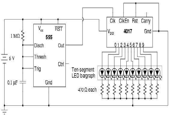
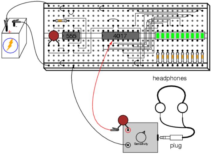
LED Squencer
PARTS AND MATERIALS
* 4017 decade counter/divider (Radio Shack catalog # 276-2417)
* 555 timer IC (Radio Shack catalog # 276-1723)
* Ten-segment bargraph LED (Radio Shack catalog # 276-081)
* One SPST switch
* One 6 volt battery
* 10 kΩ resistor
* 1 MΩ resistor
* 0.1 µF capacitor (Radio Shack catalog # 272-135 or equivalent)
* Coupling capacitor, 0.047 to 0.001 µF
* Ten 470 Ω resistors
* Audio detector with headphones
Caution! The 4017 IC is CMOS, and therefore sensitive to static electricity!
Any single-pole, single-throw switch is adequate. A household light switch will work fine, and is readily available at
any hardware store.
The audio detector will be used to assess signal frequency. If you have access to an oscilloscope, the audio detector
is unnecessary.
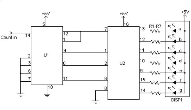
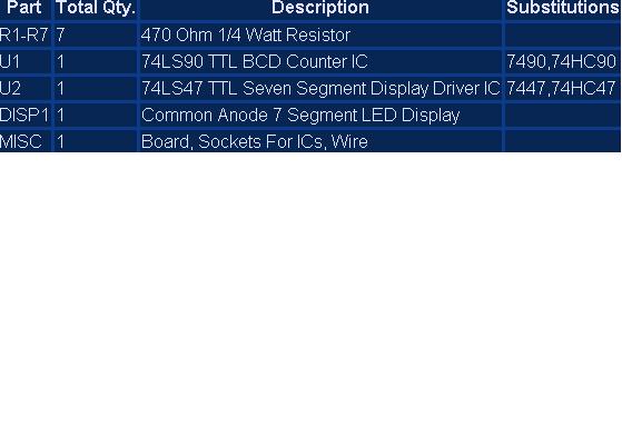
7 Segment Counter Display (SIMPLE)
Notes:
1. All pulses to be counted are to be TTL compatible. They should not exeed 5V and not fall below ground.
2. You can add more digits by building a second (or third, or fourth, etc...) circuit and connecting the pin 11-6 junction
of the 74LS90 and 74LS47 to pin 14 of the 74LS90 in the other circuit. You can keep expanding this way to as many digits as
you want.
For robotic or boe- bot application,click this
Phototropic Mobile Robot
|
